MG-Cars.info
Triumph TR6 Roll around dolly BBS discussion at MG-Cars.info

MG-Cars.info
Welcome to our Site for MG, Triumph and Austin-Healey Car Information.
Recommendations
Parts
TR parts and Triumph parts, TR bits, Triumph Car Spares and accessories are available for TR2, TR3, TR3A, TR4, TR4A, TR5, TR6, TR7, TR8, Spitfire and Stag and other TR models are available from British car spares and parts company LBCarCo.
Triumph TR6 - Roll around dolly
| Interviewed a new paint/body guy today. Among the negotiated points was for me to remove the tub, strip it and bring it to him on a roll about dolly. Now I KNOW that someone has built a wheeled dolly to roll around the tub apart from the frame. If ANYONE has and has a drawing, I'd be MOST appreciate. If no drawing perhaps someone would advise the best method of building such a device. Are the essential minimum mounting opportunities all in the same plane or must I have elevation changes to adequatey serve the purpose? What's the minimum number and location of fastening points. I have adequate support across the door openings on both sides and from side to side so would just affixing a frame across the floor pan area where the 1/2 doz or so mounting bolts are be sufficient to hold the tub for painting? That'd leave the front and rear unsupported, but is that OK? Thanks. db |
| Doug Baker |
| Hi Doug, I hate it when my threads go unanswered so I'll just chime in and say I think we need Tom C to chime in. I seem to recall he made a roll around unit like you're describing. Be sure to provide us with some pic's Good luck Henry |
| HP Henry Patterson |
| Henry, Thanks for responding. I was beginning to think that I had forgotten to bathe or something:-) TOM??? db |
| Doug Baker |
| Guys, My computer went south and Webby would not allow me to post. I have been trying to post at least 5x with no success. Tom |
| Tom C |
| Here are some pics of the door supports and dolly, I'll post a discription in another window if Webby will allow me. http://farm1.static.flickr.com/203/519099625_bfac0f5e36_b.jpg http://farm1.static.flickr.com/171/389639820_ac4285833d_o.jpg http://farm1.static.flickr.com/112/302258804_8b3e355da1_b.jpg http://farm1.static.flickr.com/113/302253073_92d58a887e_o.jpg |
| Tom C |
| Tom, that's some heavy duty stuff. I had not envisioned the dolly raising the body up so high, but why not?? Very little additional material at the outset. It appears, although hard to see, that you've supported, as I asked above, along the middle of the body on either side of the cockpit. Is that correct? No problem with the front and rear ends hanging in the air? Thanks for your response. If "Webby" denies further effort, feel free to email me directly...dbaker04ATaolDOTcom. db |
| Doug Baker |
| Tom, Here's shot of the bracing for my door openings and cross brace. I bolted up to the hinge attachment on the front and the door stricker on the B post. db 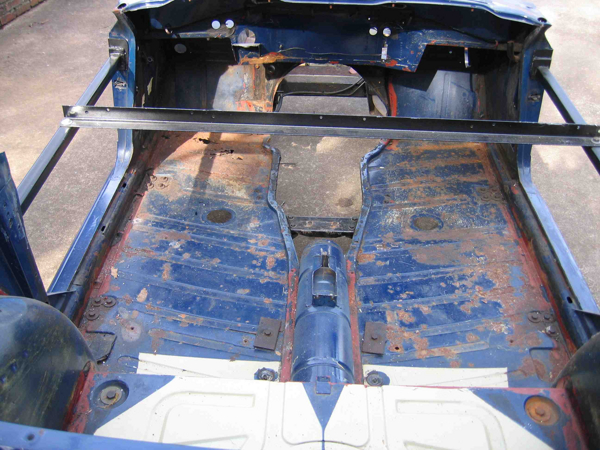
|
| Doug Baker |
| Hi Doug, The only comment I have on your bracing is that you won't be able to hang the doors when you do the final painting on the car. I intend to block sand a skim coat of filler on the doors (over some dings) with the outer fenders in place after the tube is painted. I have a 4x4 wooden post under the front and rear of the floor pans for support and to keep the sill edges from getting bent. There is no problem with the front and rear overhang, just don't put a lot of weight on it otherwise it may tip. I have the body mounted so I can paint the under carriage without laying on the floor. You're right about it being a little high, I have to stand on a picnic bench to work on top of the scuttle. Probably a better solution would be to notch the upright supports on the dolly so you can raise and lower the height of the cross supports. One option would be to use industrial racking like you see in a warehouse that has a series of holes running up the veritcal posts. One tip is not to use pneumatic casters, I have two friends that have flat tires on their carriages. Stay tuned for better pix. Tom |
| Tom C |
| Tom,I'll look for more photos. The bracing is only to maintain geometry whilst the body is removed from the frame to do the frame work and the underside of the body. The final painting will be done with the body back on the frame, now restored, and the bracing removed. db |
| Doug Baker |
| Doug, I made a body jig out of 4x4 and 2x4 lumber I had left over from a deck project (see image). I put the verticle 4x4's under all the body mounting points using deck screws and big washers and braced them like a trestle with 2x4's. It allowed me to replace the sills and floors at a comfortable level. (I think I had to remove a brace and post when I did the floors). I put some casters on it so I could turn it around and do the other side where there is more room and better light. When I was all done I put some straps on it and attached them to the rafters in the garage, raised it off the trestle jig and then lowered the body onto the frame where I finished the topside body work. Unscrewed all the 2x4 and 4x4 lumber and didn't have to worry about storing a cumbersome jig or rotisserie. Worked out pretty smart. I have more pics if anyone is interested. DS 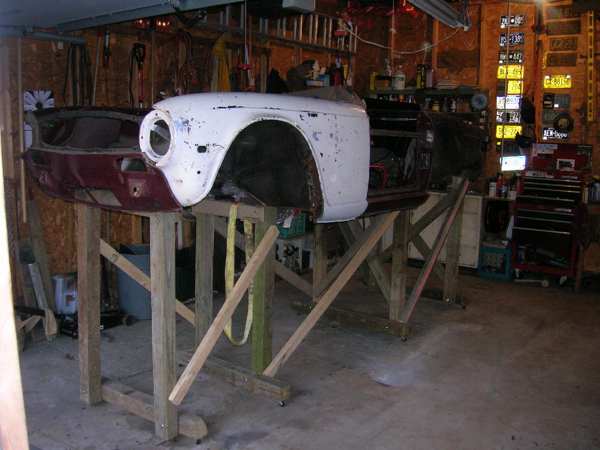
|
| Dennis Silance |
| Dennis, Impressive solution and I have just the materials having just finsihed a major deck project. I'm wondering if just the two center support sections in your jig would suffice, particularly if not too high with maybe a cantilevered suppor for the front and rear. I'm considering using 1 1/2 inch square tubing with bolts through the mounting points. This will be just to wheel around the shop whilst being painted. The metal work I need will be done with the body on the frame. What do you think? db |
| Doug Baker |
| Hi Doug, Here are some more pics of my cart. Unless you are removing the floors and sills or plan on jumping around inside the tub, I don't think you need a lot of support. I placed my braces under the front and rear of the floors which puts the A & B pillars in tension. If I were to move the supports to the wheel openings, then the top of the pillars would be in compression and I would think there would be a higher chance of buckling the floors. I placed the uprights on the ground and then welded the fore/aft tubes to create a box frame. Then I used my floor jack to raise the cart up so I could mount the casters. I found my tubing and casters by dumpster diving behind a buidling that was being condemed. Good luck, Tom http://farm2.static.flickr.com/1365/644191371_5b972071f9_b.jpg http://farm2.static.flickr.com/1191/644191339_354ae3adcc_b.jpg http://farm2.static.flickr.com/1373/644191257_ab4c466d20_b.jpg http://farm2.static.flickr.com/1060/644191199_3033cfbb5e_b.jpg |
| Tom C |
| Tom, I like your solution. I have to replace the driver's floor pan or at least the forward half of it. The body guy prefers to replace the whole panel rather than cut and weld, but...!! I also will replace both inner rocker panels and end caps. the only other replacement is the battery tray and that may again be cut and joined. I have a small hole...maybe 2 inches in the boot floor. The body guy wants to replace the whole panel. I'm not to sure about this. I also have a hole behind the left B post about an inch in dia and a 3-4 inch void about 1/2" wide behind the right B post. I like your use of the 4X4s and your mounting points are exactly where I anticipated supporting the tub. so long as no additional weight is placed on the front or rear, I'd think they'd be OK with the center well supported and I do have the door opening bracing to maintain A-B geometry. Thanks for the photos and the discussion. db |
| Doug Baker |
| Doug, I didn't know you were also replacing the floor pan. If so, don't take the car off the frame yet. Look at the inner sill carefully, it is not easy to remove by itself. In the front, there are three pieces coming together and the A pillar also rests on the inner sill. You have to peel it back to get access to the flange. http://farm1.static.flickr.com/149/389639817_31127e6feb_o.jpg In the rear, you need to remove the B pillar reinforcement and the back of the B pillar hides the joint of the inner and outer sill. http://farm1.static.flickr.com/171/389639815_4e2f281bda_b.jpg http://farm1.static.flickr.com/112/302258804_8b3e355da1_b.jpg Don't forget there are 2 angled reinforcements connecting the floor at the frame mounting points. Tom |
| Tom C |
This thread was discussed between 25/06/2007 and 30/06/2007
Triumph TR6 index